VIRFuel
For VIR Tracks see separate documentation
VIRFuel:
VIRFuel is a fuel and weight calculation application designed for Virgin Atlantic Boeing 747 / 787-9 & Airbus A340 / 330 operations using the Flywise flight plan. The application is in metric tonnes and conforms to Virgin Atlantic SOPs.
Fuel and weight data is inserted from the front page of the flight plan (the 'plan figures') and can then be updated with desired loads and actual figures from the final ZFW/loadsheet. Changes in zero-fuel weight calculate updates to trip fuel and suggest a new ramp fuel. Alternatively a manually entered ramp fuel or required extra fuel at destination will calculate updates to trip fuel and ramp fuel.
At each stage a take-off weight will be updated and TODC / OPT information calculated (a TODC buffer of 1T is used). Fuel uplift calculations in Litres and USG are available to ensure an indicated versus calculated fuel load within +/-1.5%. Finally, flight plan waypoint fuel checks can be updated for changes in trip fuel burn. Internal cross-checking is performed and aircraft limits can be set using the application settings menu. Engineers have the option to skip directly to the fuel uplift page.
Additional utilities enable track and distance data to be calculated between waypoints on a route (along with timing if groundspeed entered) and for TAF and METAR data to be downloaded for a user-defined collection of airfields.
Step 1: select aircraft - press the ℹbutton next to the TOW on page 1
Custom aircraft fields are available to provide limits not set by the default types in the menu (manually entered aircraft data is checked for consistency...)
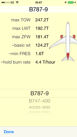
The settings allow the application to monitor several basic aircraft limitations: ZFW, TOW, LWT and minimum fuels. The ‘Engineer’ setting defaults the application to open on the fuel uplift page.
Step 2: enter data from the flywise OFP cover page
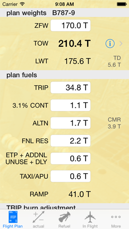
The first page of the application has a yellow background and is entitled “plan....”. This should be populated with the weights and fuels from the cover page of the flywise operational flight plan. TOW, LWT and RAMP are calculated from the other inputs. Enter the ZFW first - the application will prompt you to reset all the data for a new flight plan. If you wish to keep all the previous data (eg to correct an erroneous input) then you can but you must check the computations on succeeding pages are updated.
Once the minimum information is input the ‘LED’ next to the TOW will show green. Red indicates data outside limits, amber that the minimum data has not been entered.
The ‘+fuels’ field is a convenience for entering either ETP ADJ, ADDNL, UNUSABLE or ARR DLY. If more than 1 of these fields is used then enter the sum of the additions into this box.
Cross-check all entries against the printed data on the flight plan - the numbers should be identical. CHECK TOW AGREES WITH PLAN. Other derived information such as LWT, TD fuel, CMR and RAMP should also be cross-checked.
Once this data is validated The “FLIGHT PLAN” Page can be MODIFIED IF REQUIRED But MUST ULTIMATELY REFLECT THE DATA ON THE IN-USE FLIGHT PLAN.
Subsequent calculations are predicated on this BASELINE data - IF MODIFIED, THE ACTUAL FIGURES ON PAGE 2 (“ACTUAL”) SHOULD BE REENTERED TO REFRESH THE CALCULATIONS (consistency checking is carried out).
Step 3: enter actual ‘final’ data
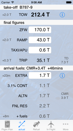
The second page is where ‘final ZFW’ weight should be entered. This page represents the actual figures which will be used for the flight (plan figures are in grey on the left side).
Enter the final ZFW: the application will calculate an updated RAMP and TRIP figure. This also allows for increased or decreased burns for fuel load change.
The formula used performs a non-iterative infinite regression of the sequence in a single expression for series addition: ∆Fuel = ∆ZFW * adjust / (1-adjust)
where ‘adjust’ is the change in fuel burn per tonne figure expressed in tonnes (eg 232kg per 1000kg is expressed as adjust = 0.232).
Fuel burn is adjusted upwards by going to the nearest 0.1T up if over 30kgs (eg 79.429 is rounded to 79.4 whereas 79.431 rounds to 79.5)
A manual figure can be inserted into the RAMP field. This will recalculate TRIP fuel and generate an EXTRA figure. This EXTRA figure is the additional amount of fuel that will remain on arrival at the destination having subtracted the increased burn from the increased RAMP. It is possible for this figure to be negative if a less than recommended RAMP fuel is used!
Alternatively a desired amount of EXTRA fuel remaining at destination can be input (for example the amount of extra holding fuel required). Using the ℹ button, this can also be input as a duration in minutes (at holding burn rate). This will generate a required RAMP and updated TRIP which takes into account fuel burned to carry this extra fuel to the destination.
The last manually entered figure (viz ZFW, RAMP or EXTRA) on which the other fuels are recalculated will be displayed in blue.
TAXI fuel can be updated if required.
TD and CMR+ fuel figures are updated to reflect the actual fuel loads.
At present other fuels cannot be adjusted (CONT, ALTN, FNL RES, +fuels) but manipulating the extra fuel (+ or -) will achieve the same result. There is also no attempt to recalculate CONT, ALTN or FNL RES on change of ZFW; again these can be compensated for by using EXTRA fuel or RAMP variations as required. In the example illustrated if an ALTN of 3.4T was required instead of the planned 1.7T then EXTRA could be set to 1.7T to make up the difference (and the RAMP is recalculated accordingly to provide this fuel at destination). Future updates will allow direct entry of such requirements.
Amber or red figures show data that is out of limits.
Select the disclosure button next to the TOW to view a representation of the ACARS TODC chit:
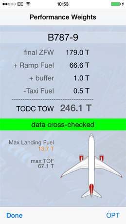
This page includes the 1T buffer for TODC TOW estimate and shows the maximum totaliser ‘TOF” fuel figure acceptable with that buffer.
Internal cross-checking of the fuel calculation integrity and limits evaluation is displayed via a status strip below the figures.
OPT can be selected which does not use the buffer and reflects the data that will be copied automatically by the OPT calculation from the FMC.
Max landing fuel is shown: It will be highlighted if it is lower than take-off fuel.
Step 4: refuelling calculations
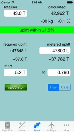
Totaliser fuel defaults to that entered as a RAMP fuel on the actual fuels page. SG defaults to 0.8 and units to Litres.
-
1.Enter the pre-refuel ‘start’ fuel figure. The grey figures under ‘required’ show the expected fuel uplift from the ‘start’ figure to the totaliser figure using the entered SG.
-
2.SG can be entered as SG, Kg/m3, lb/USG, lb/ft3: the interpretation of the input value is automatic
-
3.Enter the actual metered fuel uplift. Using the Litres/USG selector the units for the uplift can be toggled. The Tonnes equivalent is shown under this box.
-
4.At the top right of the page the calculated fuel quantity in tanks based on the start fuel plus the metered uplift is shown in tonnes to 3 decimal places (kg resolution). The difference between the calculated figure and that shown on the totaliser is displayed in Kgs and as a percentage. A ‘positive uplift’ status is generated with a percentage between -1.5% and +1.5%.
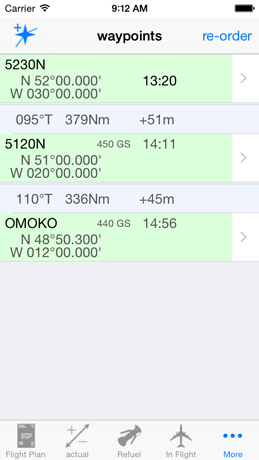
Step 4: In-flight corrections to the OFP required waypoint fuels
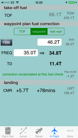
The fourth page enables corrections to be made to the waypoint fuels for changes in fuel load and burn.
-
1.TOF defaults to that expected from the actual RAMP figure minus the actual TAXI fuel from page 2. This can be updated to the actual fuel at the take-off point to provide an actual TOW (and thus effectively recalculate the trip fuel).
-
2.The initial default FREQ (fuel required) figure is that from the plan TRIP from page 1. It should thus equal the plan FREQ figure for the departure airfield as the first waypoint on the flight plan. In bold next to the plan FREQ figure is the corrected FREQ figure based on updated burn from the updated TOW.
-
3.For each waypoint entering the planned FREQ will generate an updated FREQ against which the totaliser (FOB) can be compared. The grey FOB figure in the line above is the expected totaliser quantity at the waypoint. The “min” FOB figure is an estimate of what fuel state would result in a landing at CMR with no contingency fuel available.
-
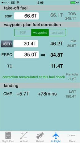
4.If required the actual totaliser quantity at each waypoint can be used in the calculation to dynamically recalculate fuel burn based on the instantaneous AUW at the waypoint (TOF will thus be ignored). To do this enable the FOB slider and insert the FOB at the waypoint. The respective waypoint FREQ from the plan should also be entered which will then be corrected based on the instantaneous AUW. The corrected FREQ subtracted from the actual FOB provides a new estimate of TD fuel using an updated burn.
-
5.The FOB button can be selected to enable the use of STARTUP FUEL minus FUEL USED to calculate the fuel on board (as with Airbus).
-
6.Use of the “waypoint” selection allows the actual fuel on board at the waypoint fuel check to be used to recalculate the deviation in gross weight of the aircraft at that particular waypoint from the planned weight at that waypoint (ie regardless of past fuel usage). The fuel burn calculation will be updated accordingly. Variations to the plan AUW are displayed.
-
7.If an actual fuel is entered against a waypoint fuel check the new burn correction can be carried forward for future plan burn adjustments by enabling the “last wpt” selection. This allows a representative fuel check to be used as the basis of the burn correction rather than the take-off fuel.
5: Track & Distance
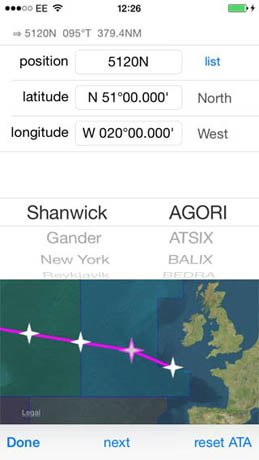
Tracks and distances can be calculated by building a string of route waypoints. Commonly used waypoints on the North Atlantic OTS are selectable by menu. The tracks are True North oriented and the distances are calculated as arcs along the ellipse between the two waypoints over the surface of the earth [elliptical] geoid. Calculation resolution is down to the order of several metres but displayed to the nearest convenient nautical mile. This method is more accurate than the spherical implementation which often generates errors in the scale of a nautical mile at mid latitudes over 10° longitude changes.
5b: Map - BETA function
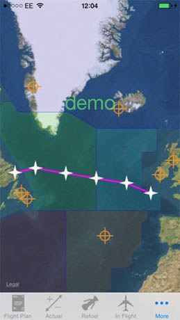
An zoomable overview map shows North Atlantic FIRs (the procedural areas) with the route list. Selected airfields are shown for which weather details are obtained by tapping the icon.
6: Weather - BETA function
Weather information is obtained from the NOAA ADDS database server. More to follow when BETA testing complete...
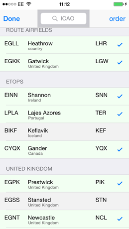
step 1: compile a list of commonly used airfields (by ICAO code) and select an active batch:
Airfields can be rearranged into regional or other specific groups.
Step 2: summary list - refresh current weather by pulling display down or using refresh control.
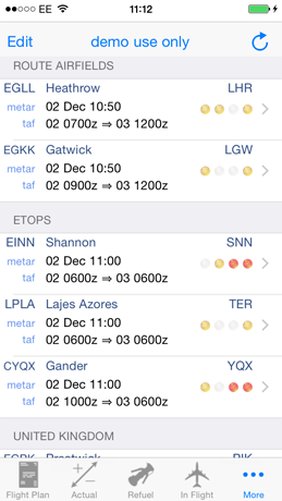
Items of potential interest are hinted at using a traffic light system (wind - visibility - weather - cloud)
Step 3: display METAR and TAF
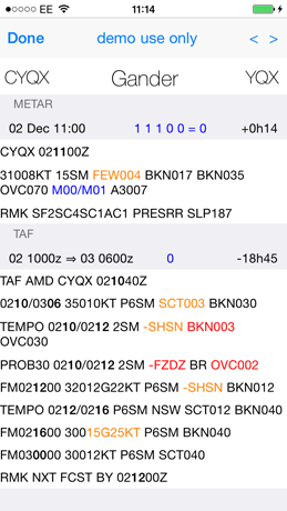
demo display... items of potential interest are highlighted. Nb the highlight algorithms on this display use a different data source and a different parsing process from the traffic light system on the summary list - this to employ a dual-source / non-common mode cross check. Expired report times are highlighted. The screen can be refreshed by pulling down the display and side-swipes can be used to select the next airfield in the list.
Although at the moment the weather system is operating as a BETA release, the data is current from the NOAA server - the BETA status reflects that the suite of comprehensive data integrity monitoring is, at the moment, only partially implemented.
More features planned - feedback via the company email address!
douglas.roxburgh@
Dougie Roxburgh 2014

